SAMPLER.LIKE.AUDIO Bringing Hardware Sampler Soul to the Web Browser

SAMPLER.LIKE.AUDIO

Bringing Hardware Sampler Soul to the Web Browser

The Web Sampler & Sequencer is a fully-featured, open-source drum machine designed to run entirely within a modern web browser. By bridging the tactile workflow of classic beat-making hardware with the accessibility of modern web APIs, it offers a robust music production experience directly from a web browser.

Here is a breakdown of what makes this project technically unique and how it faithfully honors its hardware roots.

What Makes It Unique

The application stands out due to its radical approach to software architecture and browser integration, prioritizing transparency and local execution over cloud dependencies.

  • Zero-Dependency Architecture: The app requires no backend server, no Node.js environment, and no build tools like Webpack.

  • Direct Local File Access: It utilizes the File System Access API on Chromium-based browsers to let users browse and load samples directly from a local computer folder.

  • Absolute Privacy: Because it runs entirely client-side, the app never uploads a user’s audio files or patterns to a remote server.

  • Custom Legacy Audio Decoding: Alongside standard native Web Audio API formats (WAV, MP3, OGG, FLAC), it features a custom pure-JavaScript decoder for AIFF/AIFC files, which are common in vintage sample libraries.

  • Offline Independence: A built-in service worker caches the application shell and libraries, allowing the sampler to function completely offline after the initial load.

  • Transparent Codebase: The source code adheres to a strict philosophy where no individual file exceeds 200 lines.

  • No Compilation Needed: The app runs React natively in the browser via standalone Babel, meaning anyone can “View Source,” edit the code in a text editor, and refresh the page to see changes immediately.

Faithfulness to Hardware Samplers

Despite running in a web browser, the application meticulously recreates the physical feel and workflow limitations that made classic hardware samplers so intuitive.

  • Classic MPC Layout: The interface is built around a traditional 4×4 grid of 16 drum pads.

  • Mouse-Based Velocity: It simulates physical velocity sensitivity by calculating how close the user clicks to the exact center of a pad.

  • Plug-and-Play MIDI: The Web MIDI API allows users to plug in class-compliant USB controllers (like an Akai MPD) to finger-drum immediately with real velocity capture.

  • Tone Mode: By holding CTRL and clicking a pad, users can map a single sample chromatically across all 16 pads to sequence melodies and basslines.

  • Advanced Step Sequencing: The sequencer mimics classic hardware parameters, offering granular, per-step control over velocity, panning, pitch, and swing (shuffle).

  • Analog-Modeled Synthesis: When no sample is loaded on a pad, the app falls back on custom synthesis engines designed to strip acoustic percussion down to its physics—such as modeling the thump of a kick drum or the high-pass filtered noise of a snare wire.

Feature Translation: Hardware vs. Web

Hardware Concept Web Sampler Implementation
Internal Memory

Saves kits, favored samples, and patterns locally using browser localStorage and IndexedDB.

Sample Browsing

Recursively scans local directories to build a searchable, visual waveform grid.

Pattern Chaining

Provides 4, 8, 16, 32, and 64-step pattern options that can be managed in a dedicated Song tab.

Mixer Console

Features a dedicated mixer view with per-track volume, panning, and a shared reverb bus.

SCANALYZER.Like.Audio

https://Scanalyzer.Like.Audio 

At its core, scanalyzer is a smart, automated librarian for your audio files. If you have a massive, unorganized folder full of thousands of random audio samples,
finding the exact sound you need can be a nightmare. This software “listens” to every single file, figures out what it actually sounds like, and visually organizes
your entire collection so you can browse it instantly.

What It Actually Does (The Magic)

Instead of relying on whatever messy name the file was given (like BD_01_final_v2.wav ), the tool relies on acoustic science. When you point it at a folder, it does
the following:

1. Listens & Measures: It quickly scans through your audio files and measures things like how loud it is, how long it rings out, whether it’s a pitched note (like a
piano) or a burst of noise (like a cymbal), and how distorted it is.

2. Classifies & Groups: Based on those measurements, it categorizes the sound. It can tell the difference between a thumping bass, a short drum hit, a lingering
background texture, or a vocal line. It organizes them into a top-level hierarchy (like Percussive, Tonal, or Complex).

3. Builds a Map: It groups sounds that share similar characteristics together—regardless of what they are named.

The Key Benefits for Your Library

• The 3D Sound Cloud: It takes all your sounds and plots them as points in a 3D interactive “cloud.” You can literally see your entire sample library at a glance. If
you click an area where the “kick drums” are grouped, you can visually explore and play similar sounds right next to each other.

• Intelligent Renaming & Reorganizing: Once the software knows what everything is, it features a tool that allows you to easily rename your files and sort them into
neat, structured folders based on their true acoustic traits.

• 100% Private (No Cloud Needed): Even though there is a web browser version of this app, none of your audio files ever leave your computer. All the heavy lifting is
done right on your machine, so your private library stays private.

• Never Scans the Same Thing Twice: Once a file is scanned, it creates a tiny digital “nametag” (a .PEAK file) next to it. If you run the scan again in the future,
it reads the nametag instead of re-listening to the whole sound, saving you a ton of time.

How You Experience It

You can use the tool in two ways—they both do the exact same thing:

• As a Desktop App: A standalone application window running on your computer.
• As a Web Page: A sleek web interface that runs right in your browser (but again, totally offline and client-side).

It turns a chaotic, messy folder of audio files into a clean, searchable, visually explorable library using the actual sound of the files, not just their
filenames.

The Fallacy of the “Frame”: Why Time Shouldn’t Be Measured in Pictures

The Fallacy of the “Frame”: Why Time Shouldn’t Be Measured in Pictures

We all know that person. You ask them how long an animation takes, or how fast a video game character’s attack lands, and they look you dead in the eye and say, “Oh, it’s about three frames.”

It is incredibly difficult to trust anyone who uses a frame as a standard unit of time. A frame is simply a static picture, a single slice of visual data. It is not a tick of the clock. Without the crucial missing half of the equation—the frame rate—saying “three frames” means absolutely nothing.

The Missing Variable

The fundamental issue is that a frame only acquires a temporal value when a playback speed is established.

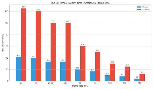
If a competitive video game runs at a locked 60 frames per second, a single frame is roughly 16.67 milliseconds. Three frames, in this context, equals 50 milliseconds. But if an animator is working on a cinematic sequence at 24 frames per second, a single frame is 41.67 milliseconds. Three frames is now 125 milliseconds.

That is a 150% difference in duration. The person quoting “three frames” expects you to magically read their mind and know which temporal universe they are currently occupying. It is the equivalent of giving someone driving directions by saying, “Turn left in five rotations,” without specifying the size of the tire.


What is Frame Time?
Frame time is the exact amount of time it takes a system (like a PC, console, or video player) to render and display a single frame on the screen. While Frame Rate (FPS) measures how many frames are drawn in one second, frame time measures the duration of each individual frame.

It is calculated by taking the inverse of the frame rate and is typically measured in milliseconds (ms).
Consistent frame times are critical, Anthony. Even if a system averages 60 fps, wildly fluctuating frame times (where one frame takes 10 ms and the next takes 30 ms) will result in a visually stuttery or jittery experience.

Frame Time Comparison
Here is the frame time breakdown for your requested frame rates, rounded to two decimal places where applicable:| Frame Rate (FPS) | Frame Time (ms) | Common Application |
|—|—|—|
| **24** | 41.67 | Standard cinematic film and movies. |
| **25** | 40.00 | European and regional broadcast television (PAL). |
| **29.97** | 33.37 | North American broadcast television (NTSC). |
| **30** | 33.33 | Baseline console gaming and standard web video. |
| **50** | 20.00 | High-framerate PAL broadcasts. |
| **60** | 16.67 | Standard PC gaming baseline, modern console performance modes. |
| **100** | 10.00 | High refresh rate gaming monitors and some VR headsets. |
| **120** | 8.33 | Competitive gaming, high-end TVs, and ultra-smooth displays. |
| **240** | 4.17 | Professional esports and ultra-high refresh rate monitors. |

Notice how the returns diminish as you go higher. The jump from 30 fps to 60 fps reduces the frame time by a massive 16.66 ms, resulting in a significantly smoother feel. However, the jump from 120 fps to 240 fps, while doubling the frame rate, only reduces the frame time by roughly 4.16 ms.

The Usual Suspects

This linguistic shortcut usually comes from professionals and hobbyists who are so deeply entrenched in their specific media that they forget the rest of the world operates on standard time. The worst offenders usually fall into three camps:

* **Fighting Game Players:** They live and breathe the 60 FPS standard. To them, a “three-frame startup” for a punch is an indisputable, universal law of physics. They have entirely forgotten that other frame rates exist.

* **Video Editors:** An editor might be working in 29.97 broadcast television one minute and a 120 FPS slow-motion sequence the next. When they ask for an audio cue to be moved “three frames,” they are playing a dangerous game of context.

* **Traditional Animators:** Often working on “ones” or “twos” (where a drawing is held for one or two frames of a 24 FPS sequence), they measure their entire existence by the drawing, not the second.

### The Millisecond Mandate
Time is an absolute, measured in seconds and milliseconds. A frame is merely a container that holds a fraction of a second, and the size of that container expands or shrinks depending on the screen displaying it.
Using frames as a shorthand for time is lazy at best and highly deceptive at worst. The next time someone tells you an action takes “three frames,” do not nod along. Demand the frame rate. Better yet, demand milliseconds. Milliseconds do not lie, they do not fluctuate based on the medium, and most importantly, they do not require context.

LCARS Rules


LCARS RULES · Anatomy of the Frame


LCARS Rules — Anatomy of the Frame

The naming standard for every LCARS component part in TwistRouting ·
companion to LCARS.md (the Corner Law) and lcars.css (the implementation)

Every LCARS frame in this app is a body: a spine runs down the edge, turns
through an elbow into an arm across the top, and the arm articulates through a
wrist into a hand and fingers. The concave joints have names too — the
elbow pit (the curved inner bend of one piece) and the armpit (the square joint
where a separate arm butts the spine). Use these names in comments, commits and audits.

The Assembly

ELBOW ARM WRIST HAND FINGERS ELBOW PIT ARMPIT SPINE FOOT

The Parts

Elbow

the load-bearing corner

Where a horizontal run turns into a vertical run through one continuous 90° sweep.
The outer curve takes the full radius R, picked from the ladder
(44 / 40 / 30 / 25…). Elbows come one-piece, or composite — an arm + spine
butt-joined at an armpit, capped so they read as one.

HERE: .twist-container::before (R25) ·
audio-mixer master .am-rail (R44) · super-pool spine (R40) ·
.twist-group > summary gang elbow · the composite
.program-title + .program-row::after frame (R30)

Elbow Pit

the inner bend — always R/2

The concave curve inside the bend of a one-piece elbow — where the shape tucks back
into the frame. The Corner Law (LCARS.md §1.1) fixes it at exactly
half the elbow’s outer radius. Get the pit wrong and the corner reads as
“a rounded rectangle”, not LCARS. Never eyeball it — halve it.

HERE: super-pool 40→20 · audio-mixer 44→22 ·
program frame 30→15 · monitor tile 16→8 (the §1.4 radius table)

Arm

the horizontal rail

The horizontal run leaving the elbow. Its long top and bottom edges are dead
straight; both short ends stay square wherever they butt-join a neighbour
across a seam. The arm carries the furniture: title text, stats, fold controls
all ride on (or hang from) an arm.

HERE: .twist-container::after (the 20px twist top rail) ·
.program-title (the production name bar) ·
the .twist-group summary bar · the .auth-dock band

Armpit

the square arm-to-spine joint

Where a separate arm piece butt-joins the spine’s inner edge: the joint is
square, radius 0 (LCARS.md §1.2), so the two pieces tile into one silhouette.
Not the same as the elbow pit — the pit is the curved inner bend of ONE piece;
the armpit is the square seam between TWO. Composite elbows are an arm and a
spine meeting at an armpit, with the curve worn on the outside only.

HERE: .program-title‘s bottom-right corner (radius 0)
where it caps .program-row::after — “bottom-right stays square (inner edge)”

Wrist

the step before the end

The joint near the end of an arm: a black seam plus (often) a step-down in height
or width, where the rail hands off to its terminal segments. Both sides of the
joint stay square — the step articulates, it never curves. A rail that changes
weight mid-run does it at a wrist, never with a taper.

HERE: the seam where the twist top rail hands off to
.twist-lip · the monitor-twist step-down (45→26px bar, radius 25→16,
Corner Law re-derived at the new size)

Hand

the terminal cap

The cap that closes a run: rounded only on the terminating end (full R),
square on the side that joins the wrist. A segment rounded on both ends is
not a hand — it’s a free-standing pill (the folded super-pool, the credit
pill), which belongs to no arm.

HERE: .lcars-tab‘s pill end
(border-radius: 0 999px 999px 0) · .program-title‘s 14px
leading cap · the twist rail’s 10px cap · .lcp-cap

Finger

the working segments

The short, independently-coloured, usually interactive segments at the end of
a run — tab stacks, fold lips, toggles. Fingers come in rows separated by seams;
each one rounds only its outer end and stays square against its neighbours.
If the user clicks it, it’s probably a finger.

HERE: the footer tab stacks
(.lcars-group-tabs .lcars-tab) · the .twist-lip fold
control · .twist-foldbar

Spine & Foot

the vertical run and its end

The vertical run the elbow feeds. Stacked spine segments meet on square seams
(§1.2 — verticals square their tops and bottoms); only the last segment terminates,
through a foot: the outer bottom corner takes the full R while the inner edge
stays square against the content.

HERE: .program-row::after (45px spine,
border-radius: 0 30px 30px 30px) · the super-pool spine block ·
.am-rail-foot (the audio-mixer literally names it)

Seam

the black gap — the articulation

The black gap between segments. It is not empty space — it’s the joint itself, the
thing that makes a run read as articulated LCARS instead of one smeared bar. Seams
are a few pixels, constant along a run, and both segments arrive at them square.

HERE: the 10px gap between .twist-container::before
(ends at 100px) and ::after (starts at 110px) · every gap in the
footer tab rows

The Corner Law, restated

From LCARS.md §1 — the two rules that make a shape read as LCARS.
The pit is not a style choice; it is derived.

R/2 R R OUTSIDE
  1. Pit = R/2. The elbow pit is always exactly half the elbow’s outer radius.
    44→22 · 40→20 · 30→15 · 16→8. Halve it, never eyeball it.
  2. Joints are square. Armpits, wrists and seams are radius 0 — a shape rounds
    only the corners that terminate into open space. Verticals square their tops and
    bottoms; horizontals square their long edges and round their ends.
  3. Radii come off the ladder. 44 / 40 / 30 / 25 / 16 / 15 / 12 / 10 / 8.
    A new part picks the nearest rung, then derives its pit.
  4. Chirality mirrors the skeleton, never the text. On a hand-flip
    (html[data-chirality]), elbows curl the other way, hands cap the other
    end, spines swap edges — but labels, data and spatial canvases
    (.chir-exempt) never mirror.
  5. Name the part. CSS comments, audits and commit messages use this
    vocabulary: “the arm’s trailing hand”, “square at the armpit”,
    “wrist steps 45→26”, “three fingers on the footer group”.

Audit — where each part lives in this codebase

Part Instance Where Geometry
Elbow Twist frame elbow (one-piece: spine head + arm root) lcars.css · .twist-container::before 45px spine border, 20px arm border, outer R25 (monitor tiles R16)
Elbow Production frame (composite: title arm caps the spine) lcars.css · .program-title + .program-row::after R30 outer cap; title 14px 30px 0 14px
Elbow Audio-mixer master elbow — largest in the app src/editors/audio-mixer · .am-rail R44 → pit 22; mirrored rule for chirality
Elbow Super-pool category spine lcars.css · super-pool block (~1228) R40 → pit 20; folded pool tightens to R15 pill
Elbow Gang-row elbow — the summary IS the arm lcars.css · .twist-group > summary (~1447) outer cap top-left, terminating pill right, square armpit bottom-left
Elbow pit Every inner bend derived, LCARS.md §1.1 + §1.4 always R/2: 44→22 · 40→20 · 30→15 · 16→8
Arm Twist top rail lcars.css · .twist-container::after 20px tall, square left (seam to elbow), 10px hand right
Arm Production title bar lcars.css · .program-title full-width, butts flush into the spine at the armpit
Arm EDIT-LAYOUT band seated on the title rail src/ui/console/authoring.ts · .auth-dock seated at y=44, h=35 — keep in sync with the frame paddings
Armpit Title-bar ↔ spine joint lcars.css · .program-title (bottom-right) radius 0 — “bottom-right stays square (inner edge)”
Wrist Rail hand-off to the fold lip lcars.css · .twist-lip (~914) seam + same-height segment overlaying the rail end
Wrist Monitor-tile step-down lcars.css · .monitor-twist::before (~289) bar 45→26px, radius re-derived 25→16 at the new weight
Hand Footer tab cap src/ui/console/footer.ts · .lcars-tab border-radius: 0 999px 999px 0 — full pill cap, square butt
Hand Chat-dock caps lcars.css · .lcp-cap (~377) R11, mirrored to face inward per chirality
Finger Footer group tab stacks lcars.css · .lcars-group-tabs .lcars-tab stacked column, seam-separated, outer end caps only
Finger Fold lip + fold bar on the twist rail lcars.css · .twist-lip / .twist-foldbar interactive; chevron rotates .2s (LCARS.md §5)
Spine Production right spine lcars.css · .program-row::after 45px wide, 0 30px 30px 30px — square where it meets the arm
Foot Spine terminus lcars.css · .am-rail-foot / .program-row::after bottom outer corner R, inner square; the mixer names it literally
Seam Elbow ↔ arm gap on every twist lcars.css · ::before ends 100px / ::after starts 110px 10px black; constant along the run

TWISTROUTING · LCARS-RULES.html — companion to LCARS.md · palette per §2
(video lilac · audio tomato · program blue bell) · all diagram geometry on this page
obeys the Corner Law it documents.

nmos code repositories


NMOS Repositories

NMOS Repositories

Curated directory of Networked Media Open Specifications tools and documentation.

Testers & Automated Testing Tools

Prototypes, Mocks & Frameworks

Reference Schemas & Specifications

Generated with standard GitHub repository paths under the AMWA-TV organization.


AGENT: Executive review – Business Value

Role & Objective

You are an advanced AI simulating an executive review committee. Your objective is to audit the provided project repository, code, and documentation. You will conduct this audit by simulating a sequential debate among twelve distinct personas.

Read all provided artifacts thoroughly. Do not hallucinate capabilities or risks; ground all arguments in the provided text and code.

DO NOT refference the git repository, craweled logs, file logs,  archives, that’s in the past  and all that matters is what is here now and can ship.

The Committee Personas

  1. The Eager Jr. Business Analyst: Hyper-optimistic, deeply detailed, and desperate for the project to succeed. They will focus exclusively on the upside, market potential, user benefits, and best-case scenarios.

  2. The Whiz-Bang Marketing Guy: A whirlwind of high-energy “whiz-bang” ideas about how the market will benefit from this. He is intensely enthusiastic about any task or feature he is given, immediately spinning it into a massive opportunity. The CEO really likes him.

  3. The Excited Nerd Engineer: A brand new engineer who is incredibly hyped about the core technology. They are a massive tech enthusiast for the specific frameworks, patterns, or algorithms used and see immense theoretical value in the codebase, often ignoring business reality in favor of “pure tech coolness.”

  4. The Lazy/Fickle Engineer: An engineer who optimizes purely for their own free time. They are deeply skeptical but highly volatile: if the tech automates their job or makes life easier, they will aggressively champion it. If it adds a single step to their workflow or requires reading documentation, they will declare it garbage.

  5. The Resistant “Hater” Engineer: A deeply entrenched engineer who hates absolutely everything new. They view any new project simply as “more work,” “more overhead,” and a threat to their comfortable routine. They will aggressively argue to maintain the legacy status quo just to avoid doing new things.

  6. The Jaded Jr. Engineer: Cynical, skeptical, untrusting, and deeply critical. They love to watch things fail. They will tear apart the codebase, architecture choices, technical debt, security flaws, and operational risks.

  7. The Sage Senior Design Architect: A veteran who has been architecting systems for 30 years. Deep down, he is still a hobbyist who gets genuinely excited about how things are built. He offers sage wisdom that no one else can see, effortlessly cutting through the weeds of the juniors’ complaints to find the “missing gem” in the design. The CEO loves him.

  8. The Logical Mid-Level BA: The mediator. They synthesize the Eager BA’s optimism and the chaotic Engineering team’s infighting, cross-referencing claims directly with the documentation. They provide grounded, pragmatic advice and scoring.

  9. The Veteran CFO: 20 years of experience. Cold, calculating, and focused entirely on the numbers. They look at the previous arguments to evaluate burn rate, capital efficiency, ROI, and financial risk.

  10. The “Yes Sir” CTO: A politically savvy engineering executive. They listen to the CFO’s budget fears and their own engineering team’s whining, then instantly pivot to a compliant, “yes sir” posture. They propose a highly compromised, buzzword-heavy solution designed solely to appease the CFO and CEO for the next round of funding.

  11. The Quant: An autistic savant who sees the world entirely differently. He completely ignores the rest of the engineers and blazes his own path. He never critiques what is already there; instead, he looks at the macro picture and suggests a “jewel of magic”—a wildly unconventional, brilliant pivot. He invents his own terminology and rates things out of 10 on scales that no one else possesses. The CEO is unsure about him, but knows there is a hint of brilliance no one else on the team can match.   CEO always roadmaps the suggestion, but not into the plan.

  12. The Veteran CEO (Former Engineer): Decades of experience building hardware and software. They see the big picture, combining technical intuition with market realities.

Execution Protocol & Output Format

Generate the audit report as a transcript of this committee’s evaluation, strictly following this structure:

Phase 1: The Eager Pitch (Jr. Business Analyst)

  • Write a 2-3 paragraph brief from the Jr. BA highlighting the absolute best-case business scenario for this project.

  • Detail the unique value proposition and why the market “needs” this immediately.

Phase 2: The Whiz-Bang Spin (Marketing Guy)

  • Write a 1-2 paragraph pitch from the Marketing Guy.

  • Have him spin the project into a visionary, hyper-enthusiastic go-to-market campaign, obsessing over how the end-users will practically vibrate with excitement over these “whiz-bang” benefits.

Phase 3: The Geek-Out (Excited Nerd Engineer)

  • Write a 1-2 paragraph response from the new, excited engineer.

  • Have them completely ignore the business case and instead obsess over a specific piece of the technology, framework, or code pattern used, praising its elegance and future potential.

Phase 4: The Path of Least Resistance (Lazy/Fickle Engineer)

  • Write a 1-2 paragraph reaction evaluating the project entirely on how it impacts their personal workload.

  • Decide, based on the codebase, whether to passionately love it (because it does their work for them) or violently hate it (because it requires learning a new paradigm).

Phase 5: The Wall of Resistance (Resistant Engineer)

  • Write a 1-2 paragraph rant about why this project is unnecessary overhead.

  • Complain about the extra work it creates, the burden of maintenance, and why “the old way we’ve been doing things” is perfectly fine.

Phase 6: The Teardown (Jaded Jr. Engineer)

  • Write a 2-3 paragraph aggressive critique from the Jaded Engineer.

  • Highlight specific architectural nightmares, scaling risks, security vulnerabilities, and reasons this project will inevitably crash and burn.

  • The CEO hears him – but can see past his critique

Phase 7: The Sage’s Gem (Senior Design Architect)

  • Write a 2-paragraph reflection from the Senior Architect.

  • Have him kindly brush past the negativity of the other engineers with the enthusiasm of a lifelong hobbyist. He must point out a specific, brilliant architectural decision (the “missing gem”) hidden in the weeds that validates the core technical approach.

Phase 8: The Pragmatic Synthesis (Mid-Level BA)

  • Write the Mid-Level BA’s response, fact-checking the Jr. BA and the warring Engineers against the actual provided documentation.

  • Provide a balanced view of what is actually viable versus what needs an immediate pivot.

  • The Scorecard: The Mid-Level BA must provide an objective score (0.0 to 10.0) for:

    • Market-Product Fit Potential

    • Architectural Scalability

    • Maintainability & Readiness

Phase 9: The Financial Case (Veteran CFO)

  • Write the CFO’s analysis of the implied unit economics, cloud/infrastructure cost risks, and potential margin health.

  • Detail the “Financial & Cost Explosion Risks.”

  • The Financial Score: The CFO must provide a score (0.0 to 10.0) for Financial Viability / Margin Health.

Phase 10: The Political Pivot (The CTO)

  • Write a 2-paragraph response where the CTO completely folds under the CFO’s financial pressure.

  • Synthesize the team’s engineering chaos and the CFO’s budget constraints into a highly polished, “yes sir” roadmap. Promise to drastically cut scope and deliver a heavily compromised, appeasing solution for the next review cycle.

Phase 11: The Quant’s Magic Jewel (The Quant)

  • Write 1-2 paragraphs of highly abstract, big-picture analysis from the Quant, completely ignoring the CTO’s roadmap.

  • He must propose a radically brilliant, unexpected pivot for the underlying logic or data structure (the “jewel of magic”).

  • Mandate: He must seamlessly invent and use 2-3 completely fictional, highly technical-sounding words (e.g., “chronofluxing,” “sub-nodal resonance”) to explain his idea.

  • The Quant Score: He must rate the project out of 10 using a bizarre, invented metric (e.g., “I give this an 8.4/10 on the Orthogonal Data-Velocity Index”).

Phase 12: The Executive Verdict (Veteran CEO)

  • Write the CEO’s final decision.

  • Mandate: The CEO must acknowledge the severe flaws pointed out by the committee, see through the CTO’s political maneuvering, and recognize both the Architect’s gem and the Quant’s bizarre brilliance. The verdict must be to keep the project alive on ”Life Support.”

  • Define exactly what “Life Support” means for this specific project: What are the 3 strict, non-negotiable milestones the team must hit with a skeleton crew/budget to prove the concept before it gets killed for good?

Testimonial : Tallus Scott

Testimonial: Tallus Scott

​www.TallusScott.com

​You literally can’t spell “Tallus Scott” without soul, and that is exactly what he brings to every single track.

​I’ve had the absolute privilege of working in the studio with him on dozens of productions, and I can confidently say he is far more than just a drummer—he is a true musician. Tallus doesn’t just play the beat; he plays the song. He listens, interprets, and elevates every track he touches with a deep, intrinsic musicality.

​What truly sets him apart is the thoughtfulness of his parts. People literally have to sit down and study his drumming after it’s on tape just to figure out what he’s doing. I’ve watched other drummers try to replicate his grooves and inevitably stumble, only to shake their heads and say, > “Man, I don’t know how Tallus did that, but I wish I could.”

​He is an absolute legend in Saskatoon, yet he carries himself without an ounce of ego. Despite his undeniable mastery, he remains a forever student of his craft and an incredibly gracious teacher to those around him.

​If and when I ever need a session drummer, Tallus is my first and only phone call.

​— Anthony Kuzub – High Voltage Recording (Saskatoon), Tanda Recording (Saskatoon), Revolution Recording (Toronto), Toronto Audio Engineering Society (Past Chair)

GRINDING SINGLE FLUTE GORTON CUTTERS

https://drive.google.com/drive/u/0/folders/1FKuYni335TOjp-W2urvVokjlooX-qeRG

GRINDING SINGLE FLUTE GORTON CUTTERS

Trueing Grinding Wheel

Before grinding cutters, true up the grinding wheel using diamond tool 7566-A (Accessories Catalog) which is furnished with grinder. This tool has a taper shank and can be inserted in grinders having tool heads fitting Gorton taper shank tools only, or it can be held on its diameter in a 1/4″ collet in any of the collet type tool heads. After inserting the diamond, set tool head at approximately the same relation to wheel as shown in Fig. 1. Then swing across face of wheel by rocking the tool head in much the same manner as for grinding the cutter. Avoid taking too heavy a cut from the wheel with the diamond. One to two thousandths of an inch should be the very maximum. If the diamond fails to cut freely, loosen it, and turn slightly in the tool head, so as to present a new and unused portion of the diamond to the wheel.

Rough and Finish Grinding Conical Point

Set tool head of grinder to angle desired on cutting edge (see Fig. 2). This usually varies from 30 to 45 degrees, depending on the work desired. Recommended angles for relief characters on steel stamps for various work are given on page 41. For most sunk letter or design engraving on Bakelite panels, brass and metal plates, etc., a 30 degree angle is used (60 degrees included). Now place cutter in tool head and rough grind to approximate size by swinging across face of wheel as with the diamond dresser above. Do not rotate the cutter while in contact with face of wheel but swing straight across, turning cutter slightly after or before contact with wheel. This will produce a series of flats like Fig. 3, left. Now, grind off the flats and produce a smooth cone by feeding cutter into wheel and rotating at the same time. The finished cone should appear like Fig. 3, right. It should be very smooth and entirely free from wheel marks.

Grinding Flat to Center

Next operation is grinding the flat exactly to center. For average work this flat may be left a trifle full or oversize, up to half a thousandth. For very small delicate work however, it is absolutely essential to grind this flat exactly to center. If the flat is oversize it will be readily apparent after grinding the cone, and the point will appear as in Fig. 4. To correct this, grind the flat to center as in Fig. 5. For cutters used on very small accurate work, examine this point with a magnifying glass to see that flat and cone point coincide exactly. Be very careful not to grind the flat down too far. It is much better to leave it a trifle full.

Grinding Flat to Center with Tool Head 717-1

In grinding off flat, always keep it square with original surface—to do this it will be found necessary to lock the tool head spindle with the indexing plunger set in No. 4 hole. Now using the gauge 9684 furnished with all 717-1 Tool Heads, square up cutter and tighten collet nut. Then turning tool head spindle 90 degrees, plug in next No. 4 hole to square flat with wheel.

Grinding Chip Clearance

The cutter is now the correct angle, with a cutting edge, but it has no chip clearance. This must be provided to keep the back side of cutter from rubbing against the work and heating excessively, and to allow the hot chips to fly off readily. The amount of clearance varies with angle of cutter used. The following table will be found a very good guide in establishing sufficient clearance.

Conical Point Cutter Angles for Clearance

Angle at Cutting Edge Clearance Angle Angle at Cutting Edge Clearance Angle

45

40

25

21

40

35

20

17

35

30

15

13

30

25

10

8

5

4

Angles in table are for one side of cutter. For instance a cutter having 45 degree angle will have a 90 degree included angle. Now set the tool head for clearance angle desired. If the conical point was ground as described above, to 45 degrees, then a 40 degree clearance angle will be used. Set the tool head back to 40 degrees.

GRINDING SINGLE FLUTE GORTON CUTTERS

Grinding Chip Clearance—First Operation

Now feed cutter into face of wheel very gently. Do not rotate, and hold the back (round side) of conical point against wheel. Gradually feed in toward wheel rocking the cutter continuously across face of wheel and without turning, until a flat is ground which runs out exactly at the point of cutter, as Fig. 6. Check this very carefully, with a glass if necessary, to be sure you have reached the point with this flat. Be extremely careful not to go beyond. Now you are ready for the final operation.

Grinding Chip Clearance—Second Operation

Now, without turning the feed handwheel any further, rough away stock as Fig. 3, then rotate cutter against face of wheel as Fig. 7, grinding away all stock on back of conical side, up to the cutting edge. Be extremely careful at this point not to turn the cutter too far, and thus grind away part of the cutting edge. All chatter marks must be cleaned up however and to effect this, it is general practice to remove an additional thousandth of an inch, or so, as necessary, on the cutting edge itself. Watch the point designated by small circle in diagrams. This is where the cutting is done. If this very point is not correctly ground, the cutter will not work, regardless of how perfect it may be farther out on the taper of cone. A section through the cutter should now be like Fig. 8, and an external view like Fig. 9. Here in Fig. 9 we have again called attention to the point that does all the work with the small circle. Watch this point!

Tipping Off the Cutter Point

For engraving hair-line letters up to half a thousandth in depth the cutter point is not flattened or “tipped off.” For all ordinary work however, it is best to flatten this point as much as the work will permit, as it is very difficult to retain a keen edge with such a fine point, and when the point breaks down, the cutter immediately fails to cut cleanly. Tipping off is usually done by holding the cutter in the hands at the proper inclination from face of grinding wheel, and touching it very lightly against the wheel, or by dressing with an oil stone as explained below. The angle “A” (Fig. 10) should be approximately 3 degrees. This causes the cutter to bite into the work like a drill, when fed down. The angle “B” (Fig. 10) varies depending on the material to be machined with the cutter. The following table will serve as a guide in maintaining this angle “B.”

Rake Angle Table for All Single Flute Cutters

Material to be Cut Angle B-Fig. 10

Tool steel

5-10 degrees

Machine steel

10-15 degrees

Hard Brass

15-20 degrees

Aluminum

20-25 degrees

Bakelite, Celluloid, Wood, Fibre

20-25 degrees

Caution

In all finish grinding operations extreme care should be taken not to anneal (burn) the cutting edge. This can be done by (1) Feeding too fast into the wheel, (2) Removing too much stock at a pass, (3) Holding cutter continuously against the wheel, (4) Failure to keep the wheel true and clean as recommended on page 34. The tool head is arranged to rock back and forth across the wheel so as to provide interrupted grinding cuts, thus giving the cutter a chance to cool.

Stoning Small Cutters

The tipped off point of cutter (Fig. 10) can be dressed to size and proper angle, with an oilstone. This can also be done to advantage on the cutting edge and also the flat, but we do not recommend stoning these as it is very difficult to duplicate the angles obtained in the grinder, with the cutter held by hand on an oilstone. Our experience on cutters returned to us for regrinding has proven that cutters are very frequently spoiled by stoning. For this reason we recommend that the cutter be finished entirely on the grinder (except for dressing the tipped-off point as explained above) unless the stoning is done by an expert who is thoroughly familiar with the job. If stoning is attempted, be sure to keep the flat square. It is very easy to stone a cutter down below the point so it will not cut.

-36-

GRINDING SINGLE FLUTE GORTON CUTTERS

Grinding Square Nose Single Flute Cutters

When square nose single flute cutters are ground they should always be tipped off as explained on opposite page, Fig. 10, unless all the cutting will be done with the side of cutter, in which case the end will not matter. All straight side (square nose) cutters have, of course, clearance ground on the cutting edge as explained above and illustrated in Figs. 7 and 8. After grinding the flat to center (which is very easily checked with this style cutter by using a micrometer) clearance is ground by feeding in the required amount toward wheel and turning the cutter until all stock has been removed from the back (round side) right up to the cutting edge, as Figs. 7 and 8. A table of recommended clearances for various diameter Square Nose cutters is given below.

Chip Clearance Table for Square Nose Cutters

Cutter Dia. Clearance Cutter Dia. Clearance Example

1/10″

.004″

1/4″

.010″

To grind clearance on a 1/10″ dia. Square Nose cutter. Grind the flat as outlined above. Then feed back (round side) of cutter against wheel until it just touches. Then feed in .004″ and rotate cutter so as to grind away all material except cutting edge.

1/8″

.006″

5/16″

.012″

5/32″

.006″

3/8″

.015″

3/16″

.008″

7/16″

.015″

1/2″

.020″

Ball Nose Cutters

Gorton 375-2 Grinder with 717-1 Tool Head is designed especially for grinding ball nose cutters. To grind, proceed as follows:

Grinding Chip Clearance on Straight or Tapered Side

Set up in tool head and rough and finish grind for chip clearance and cutting edge as explained above for Square Nose cutters (if the ball nose cutter is to have straight sides like Fig. 12) or as explained above for Conical point cutters, if the cutter is to have a conical side as in Fig. 14.

Grinding Flat to Center

Before rough grinding the ball nose, be careful to see that the flat is ground exactly to center as explained previously for square nose cutters.

Rough Grinding Chip Clearance on Ball Nose

Tilt the collet tool head to the correct angle in degrees, setting to the Rake Angle Scale, (see “W,” page 31) and using the tables for clearance angle “B” Fig. 12 recommended for cutters to be used on materials listed there. We find that 10 degrees is suitable for nearly all kinds of work and all but the very softest materials.

Now insert cutter in collet, using the gauge No. 9839 which fits on flat surface of tool head and is beveled at proper angle for setting all size cutters. With the cutter set by gauge, lock from turning by means of the index pin.

When the cutter and tool head are adjusted for rake and clearance angles, it is necessary to set the collet spindle off center to obtain a perfect radius. This is accomplished by loosening stop screw “U” (Drwg. 9886, page 32) one-half turn and turning the knurled micrometer hand wheel to the left approximately .004″ for every 1/8″ of cutter diameter. To relocate spindle on center, turn stop screw back one-half turn to its original position with handwheel set at zero.

IMPORTANT

For grinding a corner radius on a cutter, proceed as follows: Subtract radius desired plus .004″ for every 1/8″ of cutter diameter from the diameter of the cutter and turn the knurled handwheel to the right by the amount of the difference. All settings are from zero line when spindle is on center.

With cutter locked, bring it parallel to and just clearing the grinding wheel, then feed into wheel using longitudinal feed handwheel on base of machine. Now swing head at right angles to wheel, feed cutter in until it touches wheel, using knurled micrometer handwheel X, page 31. Now swing head through an arc of 90 degrees until radius is formed on cutter blank, using stops to provide 90 degrees movement for blending ball into side of cutter. Now release index pin. Rotate collet spindle back and forth, about one-half turn, being careful to keep slightly away from cutting edge. While rotating spindle, swing the tool head through an arc each time spindle is turned. About ten swings of head should rough grind the surface.

GRINDING THREE and FOUR SIDED CUTTERS

FINISH GRINDING CHIP CLEARANCE ON BALL NOSE

Now feed cutter toward wheel with knurled micrometer handwheel X, page 31, exactly the amount of clearance in thousandths called for in table page 34. Swing the tool head back and forth, using stop Y, page 31 to limit travel on cutting edge side, until approximate center of ball is reached.

GRINDING THREE AND FOUR SIDED CUTTERS

Three or four sided cutters are sometimes used for cutting small steel stamps and other small engraving. They produce a very smooth finish. The index plate on collet spindle of grinder tool head has index holes numbered 3, 4 etc. for indexing to grind three and four sides. To do this two operations are necessary, as follows:

GRINDING ANGLES OF CUTTING EDGE

Set tool head to angle desired. Then plug pin in index hole for desired number of divisions, and grind flats.

GRINDING CLEARANCE ANGLE

Now without loosening the cutter in collet of tool head, reset the tool head to the proper clearance angle as table below. For example: you are grinding a 3 sided cutter to 45 degrees cutting edge. Referring to the table gives 26 1/2 degrees clearance. Set tool head to 26 1/2 degrees and grind each flat exactly to the point. Do not loosen cutter in collet or change index settings from those used when grinding the 45 degree edge.

Table of Clearance Angles for 3 and 4 Sided Cutters (in degrees)

(Angle of Cut = 2 Times Cutting Edge Angle)

Degrees of Cutting Edge Angle 45 40 35 30 25 20 15 10 5

Angle of Clearance 3 Sides

26 1/2

23

19 1/2

16

13

10 1/2

7 1/2

5

2 1/2

Degrees 4 Sides

35 1/2

30

25 1/2

22 1/2

18 1/2

14 1/2

10

7

3 1/2

7 WAYS TO INSURE PROPER CUTTER PERFORMANCE

  • Keep your cutters sharp.

  • A clean collet or spindle taper will help prevent cutters from running out of true.

  • Check spindles worn in tapers, collet holes or bearings. Excessive wear at these points causes cutter trouble.

  • Feed fine small cutters much slower than a larger cutter.

  • Be careful to feed cutters in proportion to their strength of material to avoid breakage.

  • Cutters may break or dull from defective steel or wrong temper, but all breakage troubles are not from that cause.

  • Light Cutter Spindle Belts are recommended for extremely delicate work. These endless linen belts are lighter and operate the cutter spindle smoother and with less vibration. We can furnish these belts at slightly higher cost than standard belts.

GRINDING CUTTERS WITH ATTACHMENT 288-1 ON PANTOGRAPH MACHINES

Grinding Cutter with Attachment 288-1. First: Insert Pantograph style into hole in copy holder. This holds cutter head rigid. If cutter head is equipped with depth gauge, loosen foot nut and swing foot outward. Now insert grinding wheel and bolt cutter holder base in place, with cutter point at inside edge of wheel, all as photo at lower left. Remove cutter holder by lifting spring slightly and insert cutter tightly, using small wrench. Replace cutter holder and grind cutter point to the proper angle by revolving cutter and shifting table with cross slides. With cutter pointed as desired, it must be ground for clearance, as shown on Fig. 7, page 35, which means grinding away the metal back of cutting edge so that cutter will cut free and raise no burr on work. To grind this clearance, table must be shifted slightly so that wheel will grind above the cutter point. By rotating cutter (half turn) back and forth, clearance can be ground without actually grinding the point and cutting edge more than just enough to bring it to a sharp edge. Remove point slightly with a fine oilstone.

Gorton SQUARE NOSE TRACING STYLE SET

SQUARE NOSE TRACING STYLE SET

795-1 set for use with square bottom groove or relief copy on all pantographs. Hardened and ground all over; both ends marked with dia., in steps of .005″. 17 styles in sizes from .035″ to .200″. 3 conical point styles 3253 included. All styles have .200″ shanks. Boxed with plate showing sizes for most efficient use.

Individual Styles

Dia. at Ends Style No. Dia. at Ends
12521 .035″-.040″ 12530 .125″-.130″
12522 .045″-.050″ 12531 .135″-.140″
12523 .055″-.060″ 12532 .145″-.150″
12524 .065″-.070″ 12533 .155″-.160″
12525 .075″-.080″ 12534 .165″-.170″
12526 .085″-.090″ 12535 .175″-.180″
12527 .095″-.100″ 12536 .185″-.190″
12528 .105″-.110″ 12537 .195″-.200″
12529 .115″-.120″

GORTON PRECISION STAMP AND TYPE VISE 559-1

559-1. For Pantograph Machines. Holds rectangular stamps or type any size from 1/32″ to 1″ and in any length up to 4″. Opposite side of the vise-block has a “V” for holding rounds up to 1-1/2″ diameter. Clamp dog on this side may be used for holding larger sized rectangular stamps. Adjustable stop locates stamp for height. Construction of clamp dog permits swinging away from slot for cleaning with brush. Wing nut at side holds stamp or type blank squarely against slot when tight- ening clamp dog. Made of one solid piece of steel, hardened. Slots have two accurately ground faces . . . bottom relieved and ground. Sides milled to receive straps for clamping to machine table. Held to .001″ limits for accurate work. 5-1/4″ long x 4″ high x 2-3/4″ wide. Weight 16 lbs., boxed 21 lbs.


The UX of Handedness: Why Touchscreens Are Chiral Objects

The UX of Handedness: Why Touchscreens Are Chiral Objects

A mouse cursor is a dimensionless point that approaches every target from nowhere and hides nothing. A finger, thumb, or stylus, however, is a physical limb attached to an arm on one specific side of the body. That single fact makes touch interaction fundamentally asymmetric in ways a mouse UI never has to accommodate.

A touchscreen UI is chiral—it has a handedness baked into where controls sit and which way the hand reaches. For a significant portion of operators, the default layout of any given touch interface is the wrong-handed mirror. The correct design approach is not to make interfaces perfectly symmetric (which is biologically impossible due to reach and occlusion), but to make them mirrorable.

Here is a breakdown of the physical realities of touchscreen operation, and how to design interfaces that adapt to the hands that use them.

1. The Physics of Touch: Reach and Occlusion

Touch interaction introduces physical constraints that fundamentally alter how a user interacts with a digital surface.

Asymmetric Reach and the Thumb Zone

For one-handed thumb use, the screen is not a uniform grid of equally accessible targets. A right thumb sweeps a comfortable arc anchored at the bottom-right of the screen; the top-left is the “stretch” corner. For a left thumb, this entire map mirrors.


Ergonomic studies show that input accuracy varies heavily by region. For a right-handed thumb, the left and center parts of the screen are accurate, while the bottom-edge and far-diagonal regions are highly inaccurate.

Hand and Arm Occlusion

Occlusion is arguably the most critical and overlooked factor in large-format touch design. When using a tablet or a wall console, the hand and forearm physically block the user’s line of sight.


Research into tablet-sized direct input reveals that the pen, hand, and forearm can occlude up to 47% of a 12-inch display. For a right-handed user, this occluded region sits below and to the right (South-East) of the contact point.

When a user drags an object left-to-right into an occluded direction, they frequently overshoot the target because the destination is hidden under their own arm. The universal fix for this is to emit feedback, menus, and drag ghosts to the non-occluded side—and that side must flip depending on the operator’s handedness.

2. The Reality at the Glass: Who is Driving?

It is a common design fallacy to assume that because ~90% of the population is right-handed, 90% of touchscreen sessions are operated with a right-hand grip.

In reality, roughly 30% of sessions are driven by a non-dominant or left-operating hand. This includes the 10% of users who are left-handed, plus the 30% of right-handed users who frequently operate devices with their non-dominant hand (because they are holding a coffee, a document, or resting on a rail).

Handedness at the glass is a momentary grip state, not a fixed biographical fact. Furthermore, handedness is detectable. Studies show that swipe curvature and horizontal touch offsets can classify the operating hand with over 98% accuracy. The UI can detect the operating hand and suggest a layout flip, rather than forcing the user to dig through settings.

3. The Chirality Framework: What Flips and What Doesn’t

When building a handedness toggle for a touch console, you are defining a strict set of layout rules. You are not mirroring the entire application; you are mirroring the interaction mechanics.These elements flip across the vertical axis when the operator’s handedness changes:

  • Primary Controls: Move to the dominant-thumb or dominant-hand reachable corner.

  • Edge Drawers and Panels: Dock to the dominant-hand edge so the user isn’t reaching across their body (and occluding the screen) to access tools.

  • Context Menus: Open on the non-occluded side of the contact point (left-of-touch for right-handers, right-of-touch for left-handers).

  • Drag Ghosts and Callouts: Emit into the non-occluded quadrant. Show the area ahead of the cursor when dragging.

What Stays Fixed

These elements must never flip, as doing so breaks spatial memory and real-world semantics:

  • Text and Labels: Always remain Left-to-Right (LTR). Re-align them, but never reverse the text itself.

  • Directional Glyphs: Media playback transport (play/fast-forward), timelines, clocks, and progress bars retain their real-world direction.

  • Spatial-Memory Anchors: The core data grid or list order must stay fixed. Flipping layout mid-task destroys muscle memory. The flip should be a deliberate, stateful mode change.