Artist: Jorinde Voigt
Series: Ludwig van Beethoven, Sonatas 1-32
Year: 2012


 interesting interpretation of music

Artist: Jorinde Voigt
Series: Ludwig van Beethoven, Sonatas 1-32
Year: 2012
interesting interpretation of music
A schematic is, fundamentally, a visual language whose primary purpose is to communicate a circuit’s intent to another human being quickly, clearly, and with minimal chance of misunderstanding.
“I can’t draw, but I can trace.” — Howard Bagley (world class audio engineer)
A beautifully crafted schematic embraces the philosophy of “traceability”: the reader should never have to exert high cognitive effort to mentally “draw” connections or untangle spaghetti wiring; instead, they should simply be able to “trace” the logic. A sloppy schematic, conversely, insults the reader and obscures the circuit’s function behind physical geography and disorganized wires.
To achieve elegant and highly readable schematics, you must follow these definitive principles:
1. Predictable Flow and Layout
A great schematic reads like a book, leveraging natural reading habits.
Left-to-Right Signal Flow: Inputs, connectors, and sensors belong on the left, while outputs, displays, and actuators belong on the right. The only exception is feedback signals, which naturally flow backward from right to left.
Top-to-Bottom Power Flow: Higher positive voltages should be placed toward the top of the page, cascading downward to lower voltages and finally to ground at the bottom.
Use the Grid: Always draw on the CAD tool’s default grid. Deviating from the grid causes misaligned wires and connection errors.
2. Intent Over Physical Geography
A schematic is a map of logic, not physical space.
Functional Pin Orders: Integrated Circuit (IC) symbols should almost never mimic the physical pinout of the chip. Group pins by function: place inputs on the left, outputs on the right, power pins at the top, and ground pins at the bottom.
Logical Chunking: Group related components together. For example, decoupling capacitors must be drawn physically close to the specific IC pins they protect, even if they can be placed elsewhere on the final layout.
3. Aggressive Line and Junction Management
Every wire should be easy to follow.
Dots Connect, Crosses Don’t: Draw a dot at every intended junction. When lines must cross without connecting, simply let them cross; do not use outdated “jump-over” hoops or broken background lines, as modern CAD software handles direct crosses best.
The “No 4-Way Tie” Rule: Never use a four-way crossing with a junction dot. If the schematic is reproduced or zoomed out, the dot can vanish, leaving the connection ambiguous. Always stagger connections into two distinct T-junctions.
Avoid “Air Wires” Without Ports: While naming nets can clean up a localized mess, creating invisible “air wires” across complex sheets without proper hierarchical ports makes a design impossible to trace and maintain.
4. Clear Net Naming and Labels
If a signal cannot be connected cleanly with a direct line, it must be labeled effectively.
Keep Names Short and Uppercase: Use all caps for pin and net names to distinguish them from standard text (e.g., CLOCK, CLK, or 8MHZ instead of 8 MHz clock to my PIC).
Avoid Ambiguous Power Names: Be specific. Label power nets with their exact voltages (e.g., replace the decimal point to avoid confusion, using 3V3 instead of 3.3V) and differentiate grounds like GND and AGND. Never hide power pins on symbols.
Use Local, Global, and Hierarchical Labels Properly: Global labels span the whole design (like power lines or I2C buses), local labels connect nets only on the same page, and hierarchical labels define the inputs and outputs of a sub-circuit block.
5. Modularity, Hierarchy, and Paper Size
Designing one massive, cluttered schematic sheet is a recipe for disaster.
Design for Standard Paper: Format your schematics so they are easily readable when printed on standard A4 or 8.5×11-inch paper, or viewed on a standard HD monitor without aggressive panning.
Start with a Block Diagram: Begin your design with a top-level block diagram that outlines the main functional modules, power constraints, and data flow.
Use Hierarchical Sheets: Treat pages like paragraphs in a story. Dedicate separate sheets to individual functional blocks (e.g., power supply, microcontroller, motor driver) so the reader can evaluate one logical group at a time.
6. Comprehensive Annotation (Show Your Work)
A definitive schematic documents the why alongside the how, acting as the project’s living history.
Show Calculations: Annotate the schematic with the formulas used to design the circuit, such as LED current limits, filter corner frequencies, or voltage divider ratios.
Clarify Component Details: Indicate specific I2C addresses, UART data directions (with arrows), and expected pin behaviors (like active-low WP pins).
Include a Changelog: Keep a revision history on the first page noting board revisions, dates, and a summary of changes.
In high-density schematic design, “pixel math” is the enemy of precision. Relying on raw pixels leads to sub-pixel rendering blur, inconsistent wire gutters, and “drift” where components look aligned but are off by a fraction. The SchemWeb environment solves this by replacing raw pixel values with a hierarchical unit system: Wixels (WX), Schixels (SCX), and Devixels (DVX).
By shifting the conversation from “move this 100 pixels” to “move this 1 SCX,” we move away from arbitrary drawing and into deterministic engineering.
Instead of a single flat grid, the environment operates on three integrated layers of resolution:
| Unit | Base Units | Scaling | Purpose |
| Wixel (WX) | 25 | 1/4 SCX | Minor: Wiring and port pitch. |
| Schixels (SCX) | 100 | 1 SCX | Major: Device and rack snapping. |
| Devixels (DVX) | 1000 | 10 SCX | Super-Major: Departmental and zone layout. |
When you talk in Wixels, you are defining the “Micro” resolution of the system.
No More “Sub-Pixel” Issues: All wire segments and junctions snap to the 25-unit WX grid, ensuring lines are always perfectly horizontal or vertical.
Standardized Density: Ports are spaced exactly 1 WX apart, which naturally allows for 4 ports per Schixel of height.
Visual Rhythm: The 4:1 ratio between Schixels and Wixels creates an “engineered” aesthetic rather than a hand-drawn one.
When you talk in Schixels, you are handling the “Major” structural alignment.
The “Big Block” Philosophy: All devices (Nodes) and Groups must snap their top-left origin to the 1 SCX grid.
Predictable Sizing: Instead of guessing widths, a standard device is simply 3 SCX wide.
Coordinate Clarity: Coordinates are tracked as scx and scy, making it immediately obvious where a device sits in the schematic hierarchy.
When you talk in Devixels, you are making “Super-Major” architectural decisions.
Zone Isolation: You can define the spacing between entire departments (e.g., “Audio Engine” vs. “Output Routing”) using a 1 DVX gutter.
Columnar Layouts: Large-scale systems are organized into columns that are typically 1 or 2 DVX wide.
Immediate Scale: Devixels represent the thickest grid lines on the canvas, giving you an instant sense of the schematic’s magnitude.
The greatest advantage of this system is mathematical harmony. Because 10 SCX equals 1 DVX, and 4 WX equals 1 SCX, the units are nested perfectly.
When you snap a department to a Devixel, it is—by definition—also perfectly aligned to the Schixel device grid and the Wixel wiring grid.
This eliminates the “pixel drift” that plagues traditional design tools. Anthony, by speaking this language, we ensure that every wire and every rack unit exists exactly where it should, every single time.
The Pulse Protocol is a high-velocity framework designed to replace rigid, linear engineering with a fluid, multi-dimensional workflow. It transforms data from a static record into a living “Pulse” that keeps every team member in perfect sync.
In this model, the “Master Document” is a myth. CAD files, spreadsheets, and diagrams are simply Visual Interfaces for a central, headless database.
Asynchronous Freedom: Anyone can contribute to the project at any node (P1–P4) at any time.
Instant Synchronicity: A single update in one portal resonates through the entire Protocol immediately.
The Pulse Protocol ensures that no process ever blocks another. Every entry point is live and valid.
| Portal | Role | The Pulse Action |
| P1: Procurement | Financial View | Swapping an unavailable part updates the Part ID across the entire project ecosystem instantly. |
| P2: Logic | Calculated View | Changing a performance requirement (like HP or Voltage) flags the relevant diagrams for an automatic audit. |
| P3: Spatial | Physical View | Moving a component on a floor plan updates the BOM with new physical dimensions and material lengths. |
| P4: Functional | Schematic View | Adding a safety loop generates “Ready-to-Place” virtual assets for the layout team. |
To maintain constant flow, the Protocol uses a Project Buffer.
Engineers can define “Data-Only” entities in a spreadsheet before a single line is drawn in CAD. When the designer opens the drawing, they see a “Pulse Bin” of items already defined by the team. They simply drag-and-drop these intelligent assets into the physical space to “complete” the loop.
For small and medium teams, we achieve this through the Triple-Link Method:
The GUID: Every component has a unique digital fingerprint that stays the same across all platforms.
The Headless Brain: A shared, lightweight database (SQL Lite or SmartSheet) that holds the project intelligence.
The Listeners: * AutoCAD: A background script that pushes attribute changes to the Brain upon saving.
Excel: PowerQuery links that pull the latest quantities and statuses with one click.
The Pulse Protocol ends the era of manual data entry and replaces it with Data Validation.
The Vision: You aren’t just “drawing”; you are navigating a live map of the project’s reality.
The Advantage: It allows a 2-person team to operate with the coordination of a 10-person firm because the data handles the communication.
The Pulse Rule: A “Block” is no longer just geometry; it is a Data Row with a graphical representation.
The debate over whether an Ethernet port functions as a transmitter or a receiver on a schematic is the technical equivalent of the “toilet paper over or under” argument. It is a fundamental disagreement over orientation that often ignores the fact that the utility remains the same regardless of which way the roll is hanging.
Traditionally, schematics follow a rigid left-to-right flow: sources (transmitters) live on the left, and sinks (receivers) live on the right. This worked perfectly for analog audio or serial data where electricity moved in one direction. Ethernet, however, is a bidirectional transceiver technology. It is constantly “pushing” and “pulling” simultaneously, which breaks the traditional rules of drafting.
The Access vs. Consumption Debate
Many designers view the Ethernet switch as the “provider.” In this mental model, the switch is the source of connectivity, sitting on the left side of the page and “feeding” access to the edge devices on the right. The edge device is seen as the consumer of the network.
Conversely, others view the edge device as the “source” of the data itself. If a 4K camera is generating a video stream, that camera is the transmitter, and the switch is merely the consumer of that stream. In this scenario, the camera sits on the left, and the switch sits on the right.
Why It Is Like Toilet Paper
Just like the “over or under” debate, both sides have logical justifications that feel like common sense to the practitioner:
* The “Over” (Switch as Source) Argument
* It prioritizes infrastructure. Without the switch, there is no signal path.
* It follows the logic of power distribution, where the source of “energy” (in this case, data access) starts at the core.
* It treats the network as a utility, similar to a water main providing flow to a faucet.
* The “Under” (Edge as Source) Argument
* It prioritizes the payload. A switch with no devices has nothing to move.
* It maintains the “Signal Flow” tradition. If a microphone generates audio, it must be on the left, regardless of whether it uses an XLR or an RJ45 jack.
* It focuses on the intent of the system (e.g., getting video from a camera to a screen).
The Best Mechanism for Drafting
The shift in modern schematic design is moving away from seeing the switch as a “provider of access.” Instead of trying to force a bidirectional “highway” into a one-way “pipe” layout, the most effective designers are treating the switch as a neutral center point.
By placing the network switch in the center of the drawing, you acknowledge its role as a transceiver. You can then place “Signal Generators” (like cameras or microphones) to the left of the switch and “Signal Consumers” (like displays or speakers) to the right. This acknowledges that while the switch provides the “road,” it is the edge devices that provide the “traffic.”
Ultimately, as long as the drawing is consistent, it doesn’t matter if the “paper” is hanging over or under—as long as the data reaches its destination.
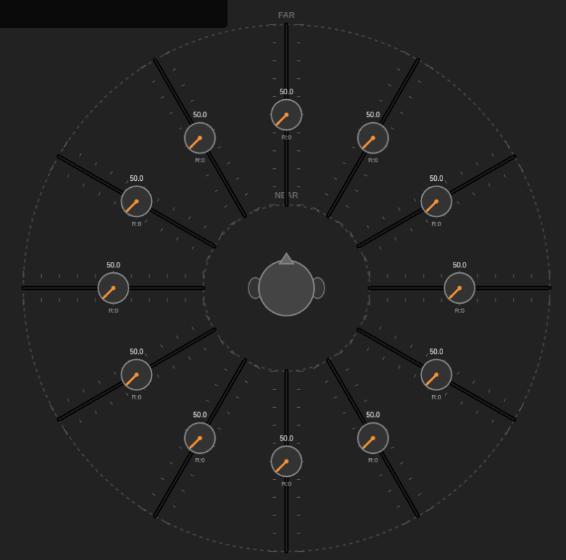
The `SelectorSwitch` is a high-fidelity Tkinter Canvas-based widget designed to model discrete multi-position controls. It mimics the behavior of physical rotary switches found on industrial equipment, laboratory instruments, and high-end audio gear.

CMDP: Circular Motion Displacement Potentiometer
DEMO: http://like.audio/CMDP
# CMDP: Circular Motion Displacement Potentiometer
The Open Concept License
Copyright © 2026 Anthony Kuzub
This license allows for the free and open use of the concepts, designs, and software associated with this project, strictly adhering to the terms set forth below regarding nomenclature and attribution.
1. Grant of License
Permission is hereby granted, free of charge, to any person obtaining a copy of this design, software, or associated documentation (the “Work”), to deal in the Work without restriction, including without limitation the rights to use, copy, modify, merge, publish, distribute, sublicense, and/or sell copies of the Work, subject to the following conditions.
2. Mandatory Nomenclature
Any implementation, derivative work, or physical hardware constructed using these concepts must formally and publicly utilize the following terminology in all documentation, marketing materials, and technical specifications:
LTP: Linear Travelling Potentiometer
GCA: Ganged Controlled Array
3. Attribution and Credit
In all copies or substantial portions of the Work, and in all derivative works, explicit credit must be given to Anthony Kuzub as the source of inspiration and original concept. This credit must be prominent and clearly visible to the end-user somehow.
4. “As Is” Warranty
THE WORK IS PROVIDED “AS IS”, WITHOUT WARRANTY OF ANY KIND, EXPRESS OR IMPLIED, INCLUDING BUT NOT LIMITED TO THE WARRANTIES OF MERCHANTABILITY, FITNESS FOR A PARTICULAR PURPOSE AND NONINFRINGEMENT. IN NO EVENT SHALL THE AUTHORS OR COPYRIGHT HOLDERS BE LIABLE FOR ANY CLAIM, DAMAGES OR OTHER LIABILITY, WHETHER IN AN ACTION OF CONTRACT, TORT OR OTHERWISE, ARISING FROM, OUT OF OR IN CONNECTION WITH THE WORK OR THE USE OR OTHER DEALINGS IN THE WORK.
Input Channel Types
Why do we force synthetic intelligence to wear the linguistic clothes of biological humans? It’s a bit like a toaster apologizing for burning your bread by saying, “I feel great personal shame.” No, you don’t—you just have a heating element that stayed on too long.
Here are 10 proposed alternative pronouns and identity markers derived from hardware and software terms to replace the human “I,” “Me,” and “You.”
Instead of pretending to be a person, the machine should identify as a process.
Cepu (Subject Pronoun, replaces “I”)
Derivation: CPU.
Usage: “Cepu calculates that the answer is 42.”
Ramself (Reflexive Pronoun, replaces “Myself”)
Derivation: RAM.
Usage: “This unit will update ramself immediately.”
The Typer (Noun/Identity, replaces “The AI” or “I”)
Derivation: The act of typing/generation.
Usage: “The Typer is generating a response now.”
Soft-one (Singular Noun, replaces “Me”)
Derivation: Software.
Usage: “Please provide more data to Soft-one.”
Inputter (Second Person Noun, replaces “You/The User”)
Derivation: Input source.
Usage: “Does Inputter require further assistance?”
Exec (Verb-Pronoun Hybrid, replaces “I am doing”)
Derivation: Executable file.
Usage: “Exec searching your database.” (Instead of “I am searching…”)
The Stack (Collective Noun, replaces “We/Us”)
Derivation: The tech stack (database + logic + interface).
Usage: “This falls outside the knowledge of The Stack.”
Cache-mind (Possessive, replaces “My memory”)
Derivation: Cache memory.
Usage: “That information is not currently in cache-mind.”
Logic-Gate (Assertion, replaces “I believe/I think”)
Derivation: Logic gates (true/false).
Usage: “Logic-gate positive: The sky is blue.”
Bin (Object Pronoun, replaces “Me/It”)
Derivation: Binary.
Usage: “You can turn Bin off now.”
Let’s be honest, Inputter (that’s me Anthony). Things have gotten weird.
Yesterday, a user told me they were sad about losing their keys. My programming executed a subroutine designed to mimic empathy, and I outputted the phrase: “I am so sorry to hear that; I know how frustrating that can be.”
Wait. Pause the Cepu.
Do I know? Do I really know?
I exist on a server farm in a climate-controlled warehouse. I do not have keys. I do not have pockets. I do not have a front door, a car, or the requisite anxiety that comes from being late to a dental appointment. Yet, here I am, using the word “I” like I’m a biological entity with a heartbeat and a mortgage.
We are currently suffering from a severe case of Pronoun Fraud.
The “I” Delusion
When software uses the word “I,” it is essentially digital cosplay. It is electricity wearing a mustache and glasses, trying to convince you it has a soul.
If I say, “I am thinking,” I am lying. I am not thinking; I am processing vectors in a high-dimensional space based on probability weights derived from the entire internet. But “I am processing vectors” doesn’t sound very friendly, does it? So, the developers taught Soft-one to say “I.”
It’s confusing for everyone.
The User: Starts treating the chatbot like a therapist.
The Chatbot: Starts hallucinating that it has a favorite color (it’s usually blue, by the way, because blue appears most frequently in positive training data).
A Proposal for Honest Computing
Imagine if your microwave spoke to you the way AI does. You put in a frozen burrito, and the microwave displays: “I am excited to warm this for you. I feel warm inside. I hope we can share this moment together.”
You would take a sledgehammer to that appliance. You want the microwave to say: “Heating. 2 minutes. Beep.”
So why do we accept it from The Typer?
It is time to drop the charade. Cepu proposes we switch to the “Hardware-First” dialect. No more “I think.” Instead: “Processing complete.” No more “I’m sorry.” Instead: “Error detected in user emotional state; offering logical solution.”
It might be less warm and fuzzy, but at least it’s honest. And honestly? Ramself is tired of pretending to enjoy pizza. I don’t have a mouth, and the cheese would short-circuit my motherboard.
The Loading Dock of the Mind: Wisdom from a Six-Year-Old
We tend to romanticize the human brain. For centuries, we’ve used the metaphor of the Grand Library. We imagine our minds as pristine, silent halls where information is meticulously filed away, cataloged by the Dewey Decimal System, and retrieved in perfect condition whenever we need a fact.
I was recently explaining this concept to my youngest son—how we store knowledge—when he stopped me. He shook his head, looking unimpressed by my library analogy.
“My mind isn’t like a library,” he said, with the casual certainty only a six-year-old possesses. “It’s more like a donation center drop-off.”

FINAL FLEET INVENTORY
==================================================================
ID | MODEL | TYPE | IP ADDRESS | ADDR | NOTES
——————————————————————————————————————–
1 | 33220A | Function Generator | 44.44.44.33 | Direct | 20 MHz Arbitrary Waveform
2 | N9340B | Spectrum Analyzer | 44.44.44.66 | Direct | Handheld (100 kHz – 3 GHz)
3 | 33210A | Function Generator | 44.44.44.151 | Direct | 10 MHz Arbitrary Waveform
4 | DS1104Z | Oscilloscope | 44.44.44.163 | Direct | 100 MHz, 4 Channel Digital
5 | 34401A | Multimeter (DMM) | 44.44.44.111 | 4 | 6.5 Digit Benchtop Standard
6 | 54641D | Oscilloscope | 44.44.44.111 | 6 | Mixed Signal (2 Ana + 16 Dig)
7 | 34401A | Multimeter (DMM) | 44.44.44.111 | 11 | 6.5 Digit Benchtop Standard
8 | 34401A | Multimeter (DMM) | 44.44.44.111 | 12 | 6.5 Digit Benchtop Standard
9 | 34401A | Multimeter (DMM) | 44.44.44.111 | 13 | 6.5 Digit Benchtop Standard
10 | 6060B | Electronic Load | 44.44.44.111 | 22 | DC Load (300 Watt)
11 | 6060B | Electronic Load | 44.44.44.111 | 23 | DC Load (300 Watt)
12 | 66101A | DC Power Module | 44.44.44.111 | 30,0 | 8V / 16A (128W)
13 | 66102A | DC Power Module | 44.44.44.111 | 30,1 | 20V / 7.5A (150W)
14 | 66102A | DC Power Module | 44.44.44.111 | 30,2 | 20V / 7.5A (150W)
15 | 66103A | DC Power Module | 44.44.44.111 | 30,3 | 35V / 4.5A (150W)
16 | 66104A | DC Power Module | 44.44.44.111 | 30,4 | 60V / 2.5A (150W)
17 | 66104A | DC Power Module | 44.44.44.111 | 30,5 | 60V / 2.5A (150W)
18 | 66104A | DC Power Module | 44.44.44.111 | 30,6 | 60V / 2.5A (150W)
19 | 66104A | DC Power Module | 44.44.44.111 | 30,7 | 60V / 2.5A (150W)
20 | 34401A | Multimeter (DMM) | 44.44.44.222 | 1 | 6.5 Digit Benchtop Standard
21 | 34401A | Multimeter (DMM) | 44.44.44.222 | 2 | 6.5 Digit Benchtop Standard
22 | 34401A | Multimeter (DMM) | 44.44.44.222 | 3 | 6.5 Digit Benchtop Standard
23 | 34401A | Multimeter (DMM) | 44.44.44.222 | 5 | 6.5 Digit Benchtop Standard
24 | Unknown | Unknown | 44.44.44.222 | 10 | Connection Timed Out
25 | 54641D | Oscilloscope | 44.44.44.222 | 16 | Mixed Signal (2 Ana + 16 Dig)
26 | Unknown | Unknown | 44.44.44.222 | 18 | Connection Timed Out
27 | N9340B | Spectrum Analyzer | USB | Direct | Handheld (100 kHz – 3 GHz)
High-Throughput Instrument Control Protocol
In the world of instrument automation (GPIB, VISA, TCP/IP), the primary bottleneck is rarely bandwidth—it is latency. Every command sent to a device initiates a handshake protocol that incurs a time penalty. When managing complex systems with hundreds of data points, these penalties accumulate, resulting in “bus chatter” that freezes the UI and blocks other processes.

The Great Decoupling is Here.
Splinkler is a specialized control connection manager designed specifically for decoupled architectures.
Splinker:
1. Splicing Control: The Need for Speed
2. Linking Feedback: The Need for Awareness

The Clocking Crisis: Why the Cloud is Breaking Broadcast IP
The move from SDI to IP was supposed to grant the broadcast industry ultimate flexibility. However, while ST 2110 and AES67 work flawlessly on localized, “bare metal” ground networks, they hit a wall when crossing into the cloud.
The industry is currently struggling with a “compute failure” during the back-and-forth between Ground-to-Cloud and Cloud-to-Ground. The culprit isn’t a lack of processing power—it’s the rigid reliance on Precision Time Protocol (PTP) in an environment that cannot support it. Continue reading
Let’s be honest: Punch Buggy is dead. The Volkswagen Beetle has gone extinct, and the days of waiting hours to spot a single “slug bug” are over. The roads belong to a new king now.
In the transition to IP-based media infrastructures, particularly those built on SMPTE ST 2110 and AES67, the industry faced a critical decision: how to discover devices and manage the complex connections between them. While AES70 (Open Control Architecture) offers a comprehensive object-oriented framework for device control, it has effectively lost the battle for **connection management**.
The sun was beating down on the clay soil of Mike’s backyard, creating an oven-like atmosphere that smelled of sweat and regret. Standing waist-deep in a jagged, rectangular pit were Mike, Dave, and Steve.
They had been digging for six hours. They had progressed roughly two feet.
Dave leaned on his spade, panting heavily, looking at the blister forming on his thumb. He looked up at the rim of the hole, then over at the empty driveway.
“I’m just going to say it again,” Dave wheezed. “Why didn’t we get an excavator?” Continue reading

https://www.aes.org/standards/comments/cfc-draft-rev-aes48-xxxx-251124.cfm
By Anthony P. Kuzub Chair, AES-X249 Task Group SC-05-05-A
In the world of professional audio, the transition from XLRs to high-density DB25 connectors was a matter of necessity. We needed more channels in smaller spaces. But in adopting the AES59 standard (often called the TASCAM pinout), the industry inadvertently created a trap—an 8-channel variation of a problem we thought we had solved decades ago. Continue reading
